


 Direct purchase from the factory

![[US DIRECT] ATOMSTACK A5 M50 APP Control Dual-Laser Laser Engraving Cutting Machine Laser Engraver Cutter 5.5W Output Power Fixed-Focus 304 Mirror Stainless Steel Engraving DIY Laser Marking for Metal Wood Leather Vinyl](https://static.roymall.com/d/file/mall/titlepic/235/67803406-41f3-499a-afb7-154990584ff8.jpg?x-oss-process=image/resize,w_237/quality,Q_80/format,webp)


![[EU/US Direct]Raiser for LONGER RAY5 Engraver](https://static.roymall.com/d/file/mall/bigpic/235/65e9b76d-574a-4b4b-9c6c-02db18b89460.jpg?x-oss-process=image/resize,w_237/quality,Q_80/format,webp)

![[US/UK Direct] Refurbished ULTIMEA Nova S70 3.1.2 Soundbar 390W True Dolby Atmos Soundbar BassMax 4K Dolby Vision HDR Passthrough 3EQ Modes Wired Speaker Subwoofer](https://static.roymall.com/d/file/mall/titlepic/235/e1440062-c78c-4565-8aa7-f8857d749771.jpg?x-oss-process=image/resize,w_237/quality,Q_80/format,webp)


1.You can contact the customer service. for any question regarding the product.
2.Ask the question in English to get answer faster.
3.Keep your question short and to the point.
Questions:0/2000

 Multi Rotor PartsFPV SystemRadios & ReceiverBattery & ChargerTools & Bags & StorageConnector & Cable & WireRC ServosElectronic Learning ToysPlane & Parachute ToysSolar Powered ToysPottery Clay & ToolsPaper Art & DrawingBlocks & Track ToysModel BuildingDiecasts & Model ToysProtective GearsMotorcycle LightsCharger & Socket AdapterMotorcycle Engines & ComponentMotorcycle HelmetMotorcycle DIY KitsMotorcycle AccessoriesMotorcycle Alarm & SecurityCar Stickers & DecalsCar CoversWindow FoilsCar Protective FilmCar Protective Film Body ArmorLicense Plate AccessoriesDIY Electronic KitsElectronic Accessories & SuppliesModule ComponentsBoard & ShieldExpansion Board & ShieldSmart ModuleSensor & Detector ModulePower Supply ModuleRaspberry Pi & Orange PiSecurity Alarm SystemSmart Remote ControlWeather Station & ThermometerAccess Control & IntercomsHome Automatic KitsAutomation ModulesClocksHome Decor StickerDecorative PaintingDecorative CraftsStorage BagsStorage BoxesItems Storage & OrganizationSeedsWatering & IrrigationGarden LightsPest Control ProductsBathroom ApplianceShowerhead & AccessoriesBathroom Storage & OrganisationBathroom SafetyDoor Hardware & LocksIndustrial HardwareDecorative HardwarePackaging & ShippingStorage & OrganizationFurniture HardwareKitchen Tools & GadgetsDrinkware & Tea SetsBakeware & AccessoriesHome Brewing & Wine MakingKitchen Knife & CutleryBarbecue & Picnic SuppliesDinnerware & FlatwareXiaomi Kitchen Appliance
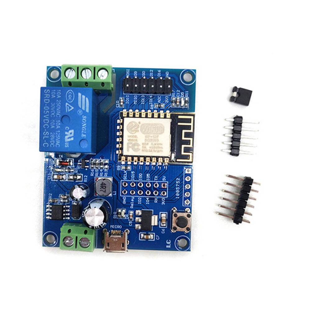
安全なチェックアウト

 無料ギフト
無料ギフト
 配送ポリシー
 返品ポリシー
Specifications:
Model: LC-Relay-ESP12-1R-D8
Color: Blue
Material: PCB
Work Voltage:DC8-80V/USB5V
WIFI IC: ESP8266
Communication Protocol:UART
Load Voltatge:AC 250V or DC 30V(Max)
Load Current:10A(Max)
Work Temperature:-25℃~85℃
Work Humidity:5%~95%RH
Features:
1. Onboard mature and stable ESP-12F WIFI module, large capacity 4M BYTE FLASH;
2. All I/O ports and UART program download ports of the WIFI module are led out to facilitate secondary development;
3. Support DC8-80V/USB5V/pin header power supply;
4. Onboard WIFI module RST reset button;
5. ESP-12F supports the use of development tools such as ECLIPSE/ARDUINOIDE, and provides reference programs under the ARDUINOs" development environment;
6. Onboard one 5V relay, output switch signal, suitable for controlling loads with working voltage within AC 250V/DC30V;
7. Onboard power indicator, 1 programmable LED and relay indicator.
Package includes:
1 x DC 5-80V ESP8266 WiFi Single Channel Relay Module
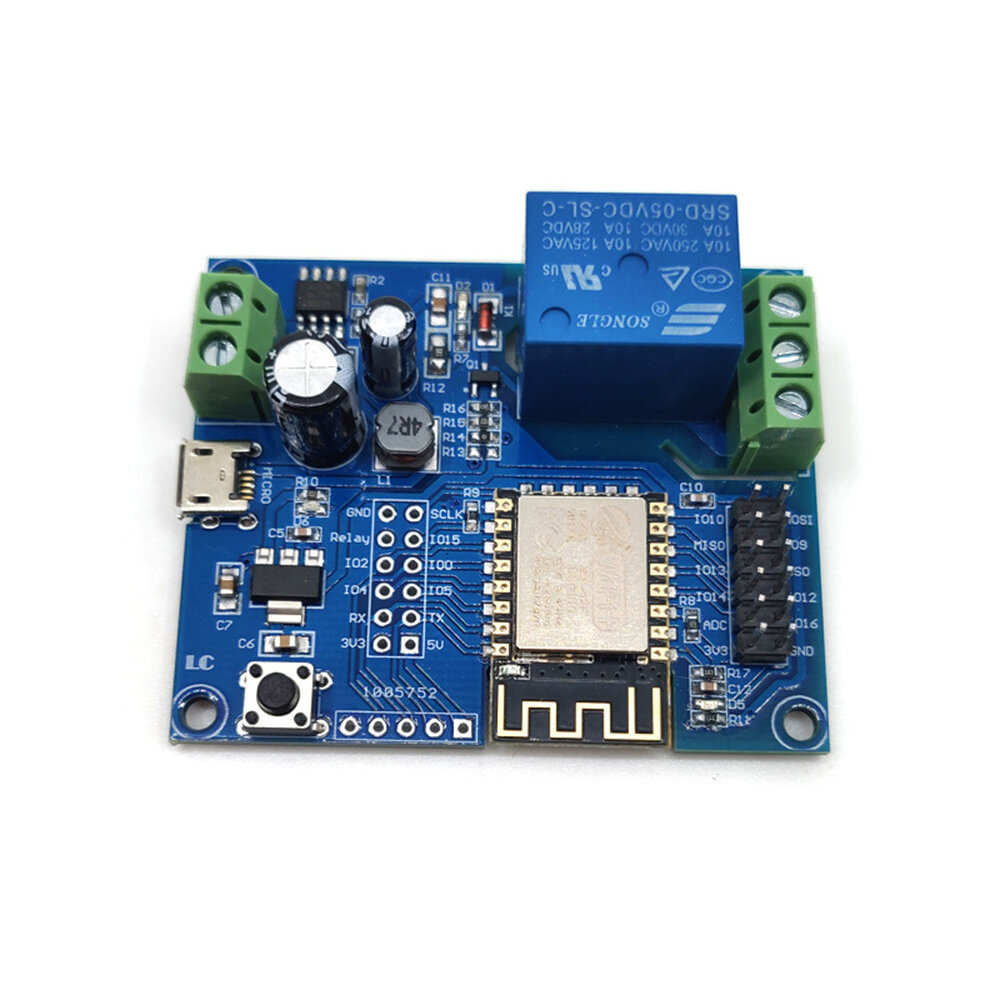
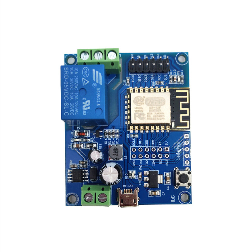
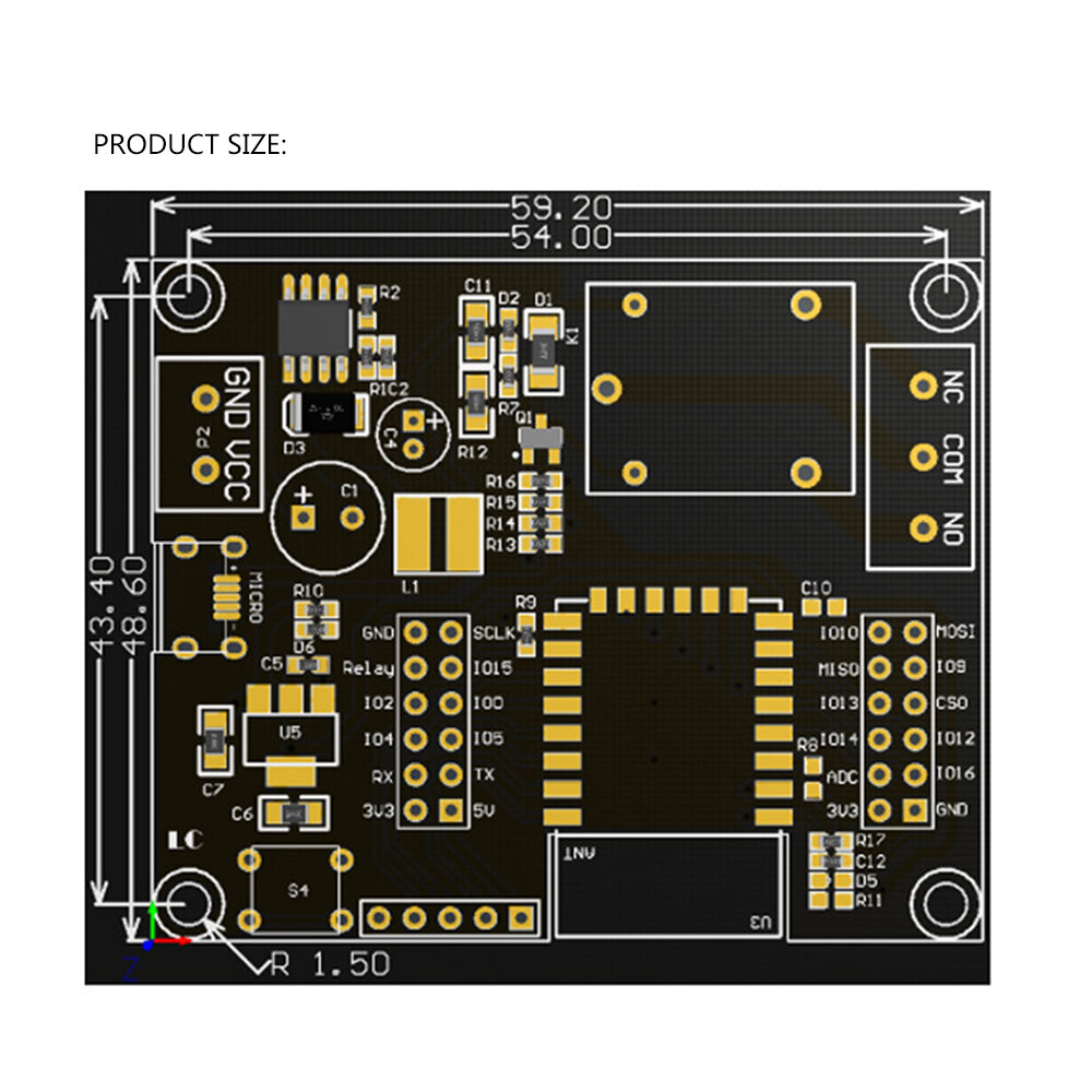
GPIO output port introduction:
| No. | Name | Function Description | No. | Name | Function Description |
1 | GND | Power ground | 13 | IO10 | GPIO10 |
2 | Relay | Relay drive port, IO5 is used as the default drive. If you want to use other I/O to drive the relay, you can remove R14 and then connect the I/O driving the relay to this Relay pin. | 14 | MISO | Slave output Master input |
3 | IO2 | GPIO2; UART1_TXD | 15 | IO13 | GPIO13; HSPI_M0SI; UART0_CTS |
4 | IO4 | GPIO4 | 16 | IO14 | GPIO14; HSPI_CLK |
5 | RX | UART0_RXD; GPIO3 | 17 | ADC | A/D conversion result. Input voltage range 0~1V, value range: 0~1024 |
6 | 3V3 | 3.3V power supply | 18 | 3V3 | 3.3V power supply |
7 | SCLK | Clock | 19 | M0SI | Host output Slave input |
8 | IO15 | GPIO15; MTDO; HSPICS; UARTO_RTS | 20 | IO9 | GPIO9 |
9 | IO0 | GPIO0 | 21 | CS0 | Chip select |
10 | IO5 | GPIO5 | 22 | IO12 | GPIO12; HSPI_MISO |
11 | TX | UART0_TXD; GPIO1 | 23 | IO16 | GPIO16 |
12 | 5V | 5V power supply | 24 | GND | Power ground |
Port Locations:
u2460 VCC, GND: DC8-80V power supply
u2461 MICRO USB: DC5V USB power supply
Note: You can choose any of the three power supply methods: DC8-80V/DC5V USB/pin header 5V
u2462 6X6MM button: ESP8266 reset button
u2463 UART program download port: ESP8266"s GND, RX, TX, 5V are connected to the GND, TX, RX, 5V of the external TTL serial port module respectively. When downloading, I0O needs to be connected to GND. After the download is completed, disconnect the connection between IO0 and GND.
u2464 GPIO pin header lead port
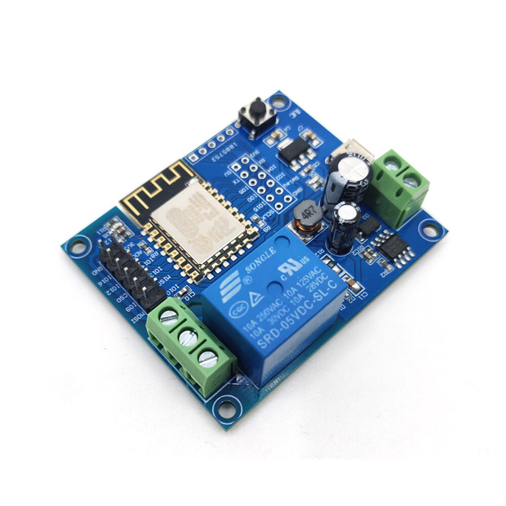
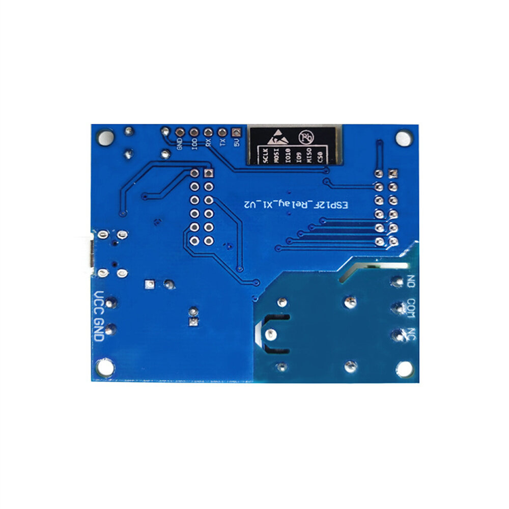
u2465 Relay output terminal
NC: Normally closed terminal, short-circuited with COM before the relay is energized, and left floating after energization;
COM: Common terminal;
NO: Normally open terminal, left floating before the relay is energized, and left short-circuited with COM after energization.
u2466 Power indicator LED
u2467 Programmable LED: controlled by GPIO16;
u2468 Relay indicator LED: lights up when energized.
A part of the review has been auto-translated.
Tips:For questions about your order, place of delivery, product discount, taxation, delivery time, warranty, shipping, payment, exchange rate, and other questions unrelated to the product, please contact customer service.
A part of the QA has been auto-translated.
 0 Liked カートに追加されました
 0 Liked カートに追加されました
 0 Liked カートに追加されました
最新のブランドニュースと初回注文15%オフを入手する。

Hi ?
How can we help?


